 Overview:
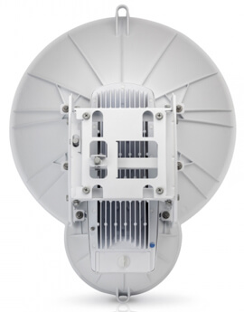
Featuring our INVICTUS™ custom silicon for 2+ million packets-per-second processing, the airFiber 24HD is ideal for outdoor, PtP bridging and backhaul applications requiring maximum performance.
Advanced Antenna System
Featuring a dual-independent 2x2 MIMO 24GHz hi-gain reflector antenna system, airFiber can operate in both FDD (Frequency Division Duplex) and HDD (Hybrid Division Duplex) modes for unparalleled speed and spectral efficiency in the 24GHz worldwide license-free band.
Revolutionary Wireless Technology
Introducing airFiber, a truly revolutionary Point-to-Point wireless platform from Ubiquiti Networks™. Housed in a compact, highly efficient form factor, airFiber delivers amazing wireless gigabit+ performance, low latency, and long range. airFiber ushers in a new era in price-disruptive wireless technology ideal for carrier backhaul, building-to-building enterprise use, or public safety applications.
Efficient by Design
Every detail of airFiber was designed and engineered by the Ubiquiti R&D Team. From the silicon chip up to the innovative split-antenna architecture, the Ubiquiti R&D Team created airFiber to deliver superior throughput with efficiency. airFiber was purposely built to create a high performance backhaul.
Plug and Play Deployment
Based on Ubiquiti’s innovative and intuitive airOS™, the airFiber Configuration Interface enables quick configuration and deployment. With installation efficiency in mind, the mechanical design allows easy installation by one person. A two-person installation crew can effectively install and align an airFiber link.
To fine-tune the alignment, the received signal levels can be conveniently accessed via any of these methods:
- airFiber LED display
- airFiber Configuration Interface
- audio tone feature
Designed for Freedom
airFiber operates in worldwide, license-free 24 GHz frequencies. Anyone around the world can purchase and operate airFiber without any special permits, paperwork, or added licensing costs. Users are free to locate, deploy, and operate airFiber practically anywhere they choose (subject to local country regulations).
Built for Speed and Range
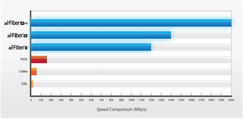
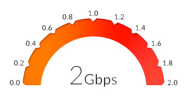
airFiber delivers gigabit performance at 1.2+ Gbps for airFiber AF-5/AF-5U, 1.4+ Gbps for airFiber AF-24, and 2 Gbps for airFiber AF-24HD. To put this in perspective, airFiber can transmit a 100 MB file in less than a second. Rivaling common broadband providers, airFiber download speed is up to 100x faster. With speed and throughput surpassing conventional wired backhauls, airFiber prevails over expensive and labor-intensive wired infrastructures.
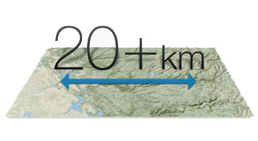
 airFiber is built for long-range use: up to 13+ km for airFiber AF-24, up to 20+ km for airFiber AF-24HD, and up to 100+ km for airFiber AF-5/AF-5U, which launches the innovative xtreme Range Technology (xRT) feature.
airFiber backhauls do not share the security risks associated with wired backhauls. The long distances of wired backhauls are vulnerable to copper theft, fiber optic damage, vandalism, and accidental breakage. With airFiber, only the installation points of the airFiber links need to be secured.
Innovative Proprietary Modem Technology
Ubiquiti's innovative proprietary modem technology was purpose-built to address the specific challenges of outdoor, PtP (Point-to-Point) bridging and high-performance network backhauls. Every aspect of the radio has been carefully simulated and designed to optimize range, speed, and latency performance in the harshest RF noise environments.
Synchronous Data Transmission and Reception
Conventional wireless standards impose a latency by having to receive a packet before a packet is transmitted. airFiber can transmit data synchronously without any wait time. airFiber features traditional TDD and FDD modes of operation in addition to the proprietary Hybrid Division Duplexing (HDD) mode, which provides a breakthrough in range and spectral efficiency performance.
Based on the ranging algorithm built into the air protocol, the airFiber radios use patent-pending HDD technology to calculate the propagation delay and know when each radio can transmit and receive, so they send packets in precise synchronization. Packet transmission latency is virtually eliminated.
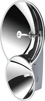
Innovative Dual-Antenna Architecture
airFiber features a dual-independent, 2x2 MIMO, high-gain reflector antenna system. Separate transmit (TX) and receive (RX) antennas help extend link budgets by eliminating the extra RF losses caused by the switches or duplexers required in systems with common TX/RX antennas.
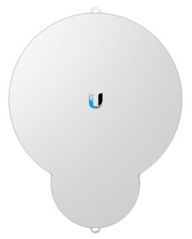
Each airFiber radio has two complete antenna systems and a mechanical back-plane that are constructed as a one-piece "monocoque" molding – a radical departure from industry practice. "Monocoque" means that the exterior skin supports the structural load of airFiber hardware. Due to its single-piece, injection-molded architecture, airFiber adds lightness in weight and affordability to its list of advantages.
Network Management
airFiber supports a variety of features to help you manage your network:
- Network management options - A choice between the greater security of out-of-band management and the convenient of in-band management.
- SNMP support - Full SNMP support to aid in network management.
- Local and remote airFiber status information - Available on the Main tab of the airFiber Configuration Interface.
Features:
Revolutionary Performance
Featuring the world’s best unlicensed-band spectral efficiency at 15.9 bps/Hz, the airFiber 24 HD supports the dense modulation rates, up to 256QAM, that are required for high data rates, up to 2 Gbps.
Proven Links: 20+ km
The airFiber 24 HD features the most powerful automatic compensation for path loss degradation due to rain fade, so it provides the best range – up to 20+ km – among 24 GHz products and allows for constellation threshold extension.
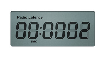
Low-Latency Carrier Backhaul
The airFiber 24 HD supports FDD (Frequency Division Duplexing) in full-duplex mode for 0.2 millisecond latency, resulting in increased efficiency for carrier-class network backhauls.
24 GHz Unlicensed Band
The airFiber 24 HD operates in worldwide, license-free, 24 GHz frequencies. Users can deploy airFiber 24HD almost anywhere they choose (subject to local country regulations).
Benefits:

Best-in-Class Performance and Range
Our INVICTUS custom silicon dramatically improves wireless performance. The AF-24HD model supports the dense modulation rates, up to 256QAM, that are required for high data rates, up to 2 Gbps. The airFiber AF-24/AF-24HD features the most powerful automatic compensation for path loss degradation due to rain fade, so it provides the best range among 24 GHz products and allows for constellation threshold extension.
Addressing the Under-served
airFiber core networks backbones can be instantly and cost-effectively deployed anywhere, bringing Internet deep into the unserved areas of the world.
Plug and Play Installation
Utilizing precision mounting hardware combined with a dynamic RSSI indicator, airFiber can be easily deployed by a single installer. Integrated GPS receivers automatically calculate position and timing parameters in the background, providing a true plug and play installation experience.
Hybrid Division Duplex (HDD)
HDD provides the best of both worlds — latency performance of Frequency Division Duplex (FDD) with the spectral efficiency of Time Division Duplex (TDD).
Breakthrough Radio Design
airFiber is the result of 100's of R&D years in radio design culminating in the most advanced, application-specific radio solution ever built for the worldwide 24GHz license-free band. It is based on a highly flexible FPGA architecture that can further be field optimized through firmware upgrades.
Superior 24 GHz Performance
Systems for millimeter-wave frequencies typically experience RF (Radio Frequency) losses, which occur when part of the RF is lost in the switches and filters. The Ubiquiti R&D team eliminated such RF losses with separate TX and RX antennas, so the link budget is robust and airFiber AF24HD has better noise figure and higher transmit power efficiency.
Robust Mechanical Assembly
An independent lab has tested the airFiber mechanical assembly to meet MIL-STD-810G, a rigorous United States MIL-STD (Military Standard) that defines a variety of challenging environmental conditions. The mechanical assembly has also undergone vibration testing using an extended version of IEC 60068-2-6, an environmental standard of the IEC (International Electrotechnical Commission).
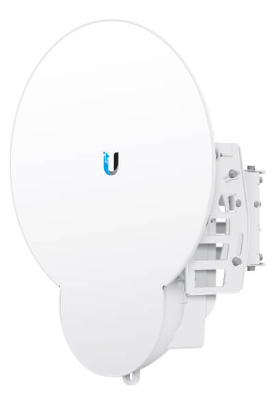
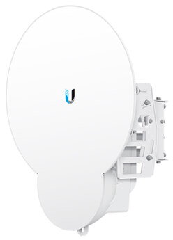
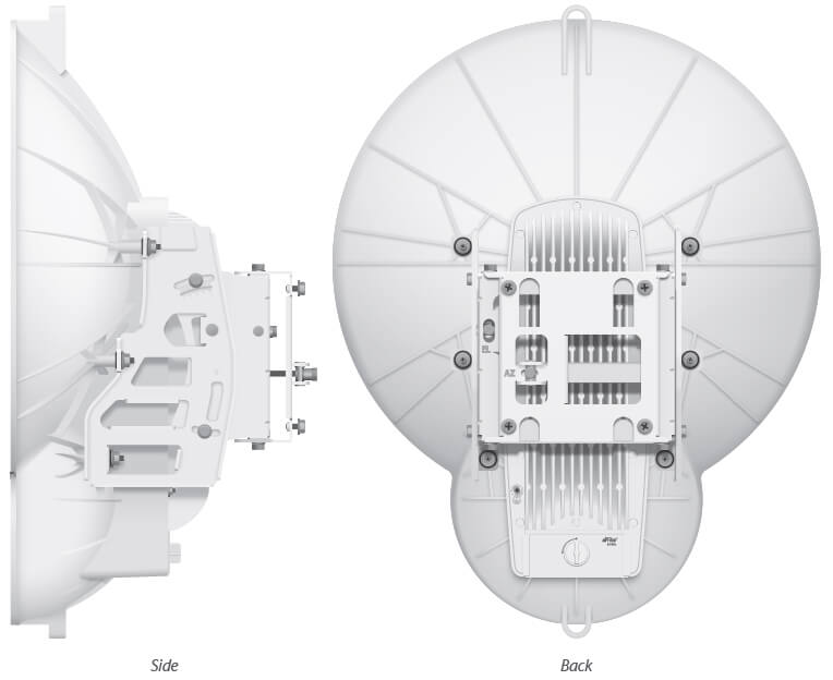
Product Views:

Specifications:
| airFiber AF-24HD Specification |
| Operating Frequency |
24.05 – 24.25 GHz |
| Dimensions |
593 x 768 x 370 mm (23.35 x 30.24 x 14.57") |
| Weight |
17.3 kg (38.14 lb) Mount Included |
| Max. Power Consumption |
50W |
| Power Supply |
50V, 1.2A PoE GigE Adapter (Included) |
| Power Method |
Passive Power over Ethernet |
| Supported Voltage Range |
42-58VDC |
| Certifications |
CE, FCC, IC |
| Wind Loading |
770 N @ 200 km/hr (170 lbf @ 125 mph) |
| Wind Survivability |
200 km/hr (125 mph) |
| Mounting |
Pole Mount Kit (Included) |
| Operating Temperature |
-40 to 55°C (-40 to 131° F) |
| LEDs |
(8) Status LEDs:
- Data Port Speed
- Data Port Link/Activity
- Configuration Port Speed
- Configuration Port Link/Activity
- GPS Synchronization
- Modulation Mode
- Master/Slave
- RF Status
- (1) Two-Digit LED Display Calibrated in dBm
|
| Data Port |
(1) 10/100/1000 Ethernet Port |
| Configuration Port |
(1) 10/100 Ethernet Port |
| Auxiliary Port |
(1) RJ-12, Alignment Tone Port |
| Maximum Throughput |
2 Gbps |
| Maximum Range |
20+ km |
| Packets per Second |
> 1 Million |
| Encryption |
128-Bit AES |
| Uplink/Downlink Ratio |
50% Fixed |
| airFiber AF24HD Radio Frequency |
| GPS |
GPS Clock Synchronization |
| EIRP |
~33 dBm (FCC/IC), ~20 dBm (CE) |
| Frequency Accuracy |
±2.5 ppm without GPS Synchronization
±0.2 ppm with GPS Synchronization |
| Channel Bandwidth |
100 MHz |
| Operating Channels |
24.1 GHz, 24.2 GHz |
| Modulation |
256QAM MIMO
64QAM MIMO
16QAM MIMO
QPSK MIMO
QPSK SISO
¼x QPSK SISO |
| TX Gain |
33 dBi |
| RX Gain |
40 dBi |
| Beamwidth |
< 3.5° |
| Front-to-Back Ratio |
70 dB |
| Polarity |
Dual-Slant Polarization |
| Cross-Polarity Isolation |
> 28 dB |
* FDD = (2) 100 MHz channels and TDD = (1) 100 MHz channel
Receive Sensitivity:
| airFiber AF-24HD Receive Sensitivity |
| 256QAM |
-60 dBm |
2000 Mbps |
1024 Mbps |
| 64QAM |
-66 dBm |
1500 Mbps |
760 Mbps |
| 16QAM |
-72 dBm |
1000 Mbps |
507 Mbps |
| QPSK MIMO |
-78 dBm |
500 Mbps |
253 Mbps |
| QPSK SISO |
-80 dBm |
250 Mbps |
127 Mbps |
| ¼x QPSK SISO |
-87 dBm |
62.5 Mbps |
31.7 Mbps |
Design Guide:
Getting the Most from a Versatile Platform
The airFiber AF24 is a versatile platform that can be optimized for a variety of conditions. The user interface is simple and intuitive, but there are numerous configuration parameters. The AF24 is a veritable Swiss Army knife when it comes to versatility and options to address different needs.
Configuration for Ultimate Speed and Latency Performance
Typically the best speed and lowest latency will be obtained with the AF24 configured as a full-duplex system using Frequency Division Duplexing (FDD). The data streams generated by the AF24 are simultaneously transferred across the wireless link. The transmitter and receiver are running concurrently in time. Because of the trade-off between bandwidth resources and propagation conditions, this approach is typically reserved for links in areas where installations are in clear line-of-sight conditions and free of reflected energy such as that generated by heavy rain or intermediate objects. Installations that are subject to Fresnel reflections or highly scattered environments may experience some level of degradation at great range.
For Full Duplex mode, the TX and RX Frequencies should be different.
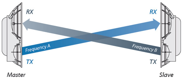
Full-Duplex Diagram
Configuration for Highest Possible Availability and Robustness
Links that are installed in environments that are highly reflective or subject to considerable scattering due to heavy rain or foliage loss are typically better suited to half-duplex configurations. In this case the frequency and bandwidth resources are shared on a Time Division Duplexing (TDD) basis, and the system can accept higher levels of propagation distortion. The trade-offs are reduced throughput and slightly higher latency.
For Half Duplex mode (default), the TX and RX Frequencies can be the same or different to suit local interference.
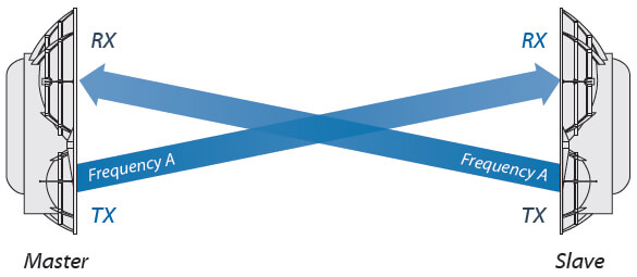
Half-Duplex Diagram
The AF24 radio system has the ability to manage time and bandwidth resources, similar to other systems utilizing different modulation schemes that are scaled according to the noise, interference, and quality of the propagation channel. The AF24 system also automatically scales its modulation based on channel quality but has the ability to be reconfigured from a time/bandwidth perspective to allow for best possible performance. In many regards the suitability of the duplexing scheme needs to be taken into account based on the ultimate goals of the user. Just as channel conditions have an effect on the modulation scheme selection, there are effects on duplexing modes to consider as well.
Alignment
Tips
- We recommend using a pair of installers in constant communication because in the fine-tuning stage, one installer makes azimuth and elevation adjustments on one airFiber radio while the other installer reports the received signal level at the other airFiber radio. (Fine-tuning is necessary because the main lobe of the receiver is more narrow than that of the transmitter, in both azimuth and elevation.)
- To accurately align the airFiber radios for best performance, you MUST align only one end of the link at a time.
- As a safety precaution, ground the airFiber radios to grounded masts, poles, towers, or grounding bars. Use ground wires with a minimum diameter of 8 AWG (10 mm2) and a maximum length of 1 meter. For guidelines about grounding and lightning protection, follow your local electrical regulatory codes.
- For more convenient alignment, you may consider using long-range scopes (not included) temporarily attached to your airFiber radios.
- You may need to use additional hardware to compensate for issues such as the improper orientation of a mounting pole or significant elevation differences between the airFiber radios.
Establishing a Preliminary Link
Adjust the positions of the airFiber radios to be within a few degrees of the line of sight between them. The Master must be aimed first at the Slave because the Slave does not transmit any RF signal until it detects transmissions from the Master.
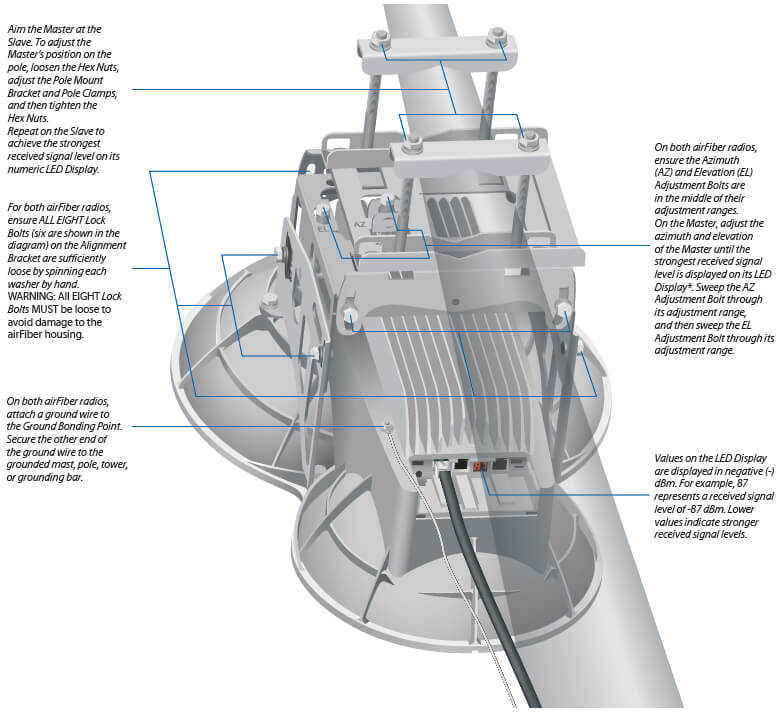
Fine-Tuning the Link
The Azimuth (AZ) and Elevation (EL) Adjustment Bolts of the Alignment Bracket adjust the azimuth and elevation within a range of ±10°. For accurate alignment, make adjustments on one end of the link while the other installer reports the received signal level at the other end of the link.
Note: Do NOT make simultaneous adjustments on the Master and Slave.
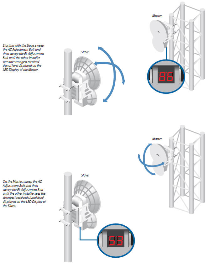
Alternate adjustments between the airFiber radios, until you achieve a symmetric link, with the received signal levels within 1 dB of each other. This ensures the best possible data rate between the airFiber radios.
Lock the alignment on both airFiber radios by tightening all eight Lock Bolts on the Alignment Bracket. Observe the LED Display on each airFiber AF24 to ensure that the value remains constant. If the LED value changes during the locking process, loosen the Lock Bolts, finalize the alignment of each airFiber AF24 again, and retighten the Lock Bolts.
Summary
The following summarizes these guidelines. We have seen installations that greatly deviate from these guidelines yet still work very well. Each installation is different and will need to be optimized based on the conditions present in the field and the goals of the user.
Frequency Division Duplexing (FDD) is best for:
- Maximum possible throughput
- Minimum possible latency
- Installations that are free of reflective and scattering elements
- Areas that see lower amounts of rainfall
- Scenarios with more available spectrum
Time Division Duplexing (TDD) is best for:
- Co-location with other master nodes
- Robustness in areas that see the most rainfall
- Scenarios with less available spectrum
- Less than ideal installations, such as installations near obstructions or scattering elements
These guidelines are only general recommendations. For example, we have successfully co-located FDD links and installed FDD links that work on a single frequency at short range.
Technology:
airFiber Radio
- Superior Throughput with No RF Losses
- Innovative Zero IF Radio
- Flexible FPGA Architecture
- Revolutionary Media Access Control
- Multiple Input, Multiple Output Spatial Multiplexing
- Time and Bandwidth Resource Management
Superior Throughput with No RF Losses
Starting with the silicon chip, the Ubiquiti Networks™ Research and Development (R&D) team created airFiber, a sophisticated system robust enough to perform in the harshest RF noise environments. Designed for high-performance backhauls and outdoor, PtP (Point-to-Point) bridging, airFiber AF24 efficiently delivers up to 1.5+ Gbps, aggregate throughput.
Systems for millimeter-wave frequencies typically experience RF (Radio Frequency) losses, which occur when part of the RF is lost in the
switches and filters. The R&D team eliminated such RF losses, so the link budget is robust and airFiber has better noise figure and higher
transmit power efficiency.
Innovative Zero IF Radio
Designed with two multiplexed transmitters and two multiplexed receivers, the airFiber radio is Zero IF (Intermediate Frequency); it is a
direct-conversion radio that generates and decodes the received signal at baseband, so there is no intermediate frequency and virtually
no signal loss between the radio and antenna. The R&D team invented numerous algorithms to control the amplitude and phase. The
end results are excellent spectral shape and freedom from spurious responses that stem from conversion by-products.
Flexible FPGA Architecture
The highly flexible FPGA (Field Programmable Gate Array) architecture can be further field-optimized through firmware upgrades.
airFiber features both sophistication and reprogrammability; you can add features as they become available and enhance system
performance through firmware upgrades.
Revolutionary Media Access Control
The R&D team created a new MAC (Media Access Control), which is the link between the radio control (FPGA) and physical network.
All real-time packet processing is placed in dedicated parallel hardware rather than in software. All real-time functions related to digital
signal processing and coding are handled in fully custom hardware that is reconfigurable, so the MAC is extremely powerful while
retaining the inherent flexibility of a software-defined system.
Multiple Input, Multiple Output Spatial Multiplexing
airFiber incorporates an OFDM (Orthogonal Frequency Division Multiplexing) system to use linear, 2x2, MIMO (Multiple Input, Multiple
Output) spatial multiplexing, which has two benefits: enhanced spectral efficiency and the ability to maintain reliable links in poor
propagation environments.
Time and Bandwidth Resource Management
airFiber automatically scales its modulation based on channel quality but has the ability to be reconfigured from a
time/bandwidth perspective to enable the best possible performance in a wide variety of deployment scenarios.
Dual-Antenna Architecture
- Innovative Dual-Antenna Architecture
- Synchronous Data Transmission and Reception
- Robust Mechanical Assembly
Innovative Dual-Antenna Architecture
The Ubiquiti Networks™ R&D (Research and Development) team created airFiber for
outdoor PtP (Point-to-Point) bridging and high-performance network backhauls.
The team invented a market-leading, dual-antenna architecture. Each airFiber
unit features a radical departure from industry practice: a one-piece "monocoque"
molding comprising two complete antenna systems and a mechanical back-plane.
"Monocoque" means that the exterior skin supports the structural load of the airFiber
hardware; this same concept is used to construct lightweight, rigid structures, such
as those used for Formula One race cars. Due to its single-piece, injection-molded
architecture, airFiber adds lightness in weight and affordability to its list of advantages.
Synchronous Data Transmission and Reception
If airFiber had been constructed using conventional methods and individual
mechanical parts, collimation distortion (the two antenna beams being skewed with
respect to one another) would likely have a negative impact on link budgets and
overall system performance. With airFiber's innovative, one-piece assembly, the two
antennas can be aimed at exactly the same point in space with a high degree of
accuracy and repeatability.
airFiber features a dual-independent, 2x2 MIMO, high-gain reflector antenna system.
On each airFiber unit, the smaller antenna on the bottom transmits, and the larger
antenna on the top receives. The main lobe of the receiver is more narrow than that
of the transmitter, in both azimuth and elevation, so peak performance requires
precise aiming and fine-tuning of the alignment between the airFiber units during
installation.
Robust Mechanical Assembly
An independent lab has tested the airFiber mechanical assembly to meet
MIL-STD-810G, a rigorous United States military standard that defines a variety
of challenging environmental conditions. The airFiber mechanical assembly has
also undergone vibration testing using an extended version of IEC 60068-2-6, an
environmental standard of the IEC (International Electrotechnical Commission). By
industry standards, the typical test looks for no observable mechanical failures after
3 hours of sinusoidal sweeps. The airFiber R&D team set the bar higher for airFiber,
which passed an extended, 3-axis test that ran for 9 hours to ensure no mechanical
failures. (Extended 9-hour testing is often done for MIL-STD compliance.)
Software:
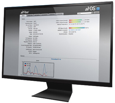

Loaded with Powerful Features
airOS F is an intuitive, versatile, highly developed Ubiquiti firmware technology that resides on airFiber. It is exceptionally intuitive and was designed to require no training to operate. Behind the user interface is a powerful firmware architecture which enables hi-performance network backhauls.
airOS F Tools
- Speed Test
- Antenna Alignment
- Device Discovery
- Site Survey
- Ping
- Traceroute
airOS F Integrated Technologies
airFiber’s purpose-built hardware provides superior wireless performance, higher capacity, and lower latency. Unlike standard WiFi protocols, Ubiquiti airFiber’s Hybrid Division Duplex (HDD) provides the best of both worlds — latency performance of Frequency Division Duplex (FDD) with the spectral efficiency of Time Division Duplex (TDD).
Wireless Modes
Wireless Network Configuration
- Transmit Frequency
- Receive Frequency
- Output Power
- Modulation Rate
- Automatic Modulation Rate Adaptation
- Duplex: Half or Full
- High/Low RX Gain
- Wireless Security: AES-128
Network Mode
- Transparent Layer 2 Bridge
Network Configuration
- In-Band Management
- Management VLAN
Management
- Automatic check for airOS F Updates
- Configuration Test Mode
- Firmware Recovery via TFTP
- Reset to Factory Defaults
- Configuration Management: Backup/Restore Device Configuration
- Administrator/Read-Only Access
- WEB/SSH/Telnet Access
- Dynamic DNS
- NTP Client
- Ping Watchdog
- SNMP v1 Support
- System Log: Local/Remote
- Full Statistical Performance Reporting
Tools
- Speed Test
- Antenna Alignment
- Device Discovery
- Ping
- Traceroute