
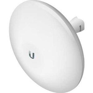
Ubiquiti NanoBeam M2 All-in-One Design
High-Performance airMAX Bridge
Sorry, this product is no longer available, Please contact us for a replacement.
Overview:
The NanoBeam M has a compact, all-in-one design with uniform beam width, efficient footprint and a faster processor. The NanoBeam can be easily mounted in a variety of ways thanks to the innovative mechanical design.
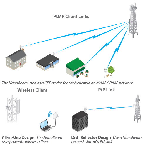
Starting with the first-generation NanoBridge, Ubiquiti Networks™ pioneered the all-in-one design for an airMAX product functioning as a CPE (Customer Premises Equipment). Now Ubiquiti Networks launches the latest generation of CPE, the NanoBeam™.
Improved Noise Immunity
The NanoBeam directs RF energy in a tighter beamwidth. With the focus in one direction, the NanoBeam blocks or spatially filters out noise, so noise immunity is improved. This feature is especially important in an area crowded with other RF signals of the same or similar frequency.
Integrated Design
The NanoBeam models are available in two form factors:
- All-in-One Design
The Ubiquiti Research and Development team combined the radio and antenna to create a more efficient and compact CPE. The NanoBeam gets maximum gain out of the smallest footprint. - Dish Reflector Design
Ubiquiti's InnerFeed™ technology integrates the radio into the feedhorn of an antenna, so there is no need for a cable. This improves performance because it eliminates cable losses.
Providing increased performance from its faster processor and innovative mechanical design at a low cost, the NanoBeam is extremely versatile and cost-effective to deploy.
Application Examples
Utilize airMAX Technology
![]() Unlike the standard WiFi protocol, Ubiquiti's Time Division Multiple Access (TDMA) airMAX protocol allows each client to send and receive data using pre-designated time slots scheduled by an intelligent AP controller.
Unlike the standard WiFi protocol, Ubiquiti's Time Division Multiple Access (TDMA) airMAX protocol allows each client to send and receive data using pre-designated time slots scheduled by an intelligent AP controller.
This "time slot" method eliminates hidden node collisions and maximizes air time efficiency. It provides many magnitudes of performance improvements in latency, throughput, and scalability compared to all other outdoor systems in its class.
- Intelligent QoS - Priority is given to voice/video seamless streaming.
- Scalability - High capacity and scalability.
- Long Distance - Capable of high-speed, carrier-class links.
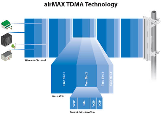
Up to 100 airMAX stations can be connected to an airMAX Sector; four airMAX
stations are shown to illustrate the general concept
Features:
Innovative Mechanical Design
- All-in-one design - The NanoBeam provides both the radio and antenna in the smallest possible footprint.
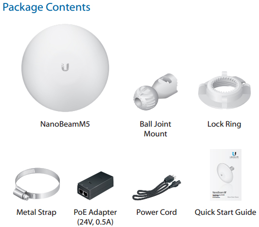
- Quick and easy installation - No fasteners are required for pole-mounting, and a single wall fastener (not included) is required for wall-mounting.
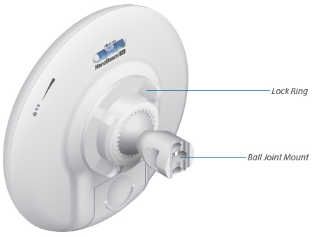
- Convenient alignment - The NanoBeam pivots on its ball joint for easy aiming.
Compact Form Factor
- Efficient footprint - The radio and antenna are combined into a single body that takes up minimal space.
- Versatile mounting - The NanoBeam can be mounted in almost any position needed for line of sight.
- Aesthetics - The NanoBeam is small enough to blend discreetly into the background at a customer's location.
Plug and Play Installation
The NanoBeam mounts to a variety of surfaces including poles or walls, and offers the freedom of three-axis alignment. No screws are required for pole-mounting, and only a single wall screw (not included) is required for wall-mounting.
Incredible Antenna “Beam” Performance
The form factor of the NanoBeam features the highest gain for its size. The NanoBeam’s excellent beam directivity provides the best performance in high-noise environments.
Advanced Software Technology
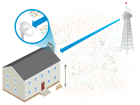
Ubiquiti’s airMAX technology is proven in millions of deployments worldwide, exhibiting outstanding performance in outdoor environments. The TDMA airMAX protocol enables unprecedented scalability, high throughput and low latency in unlicensed, multipoint networks.

Wall Mount Kit
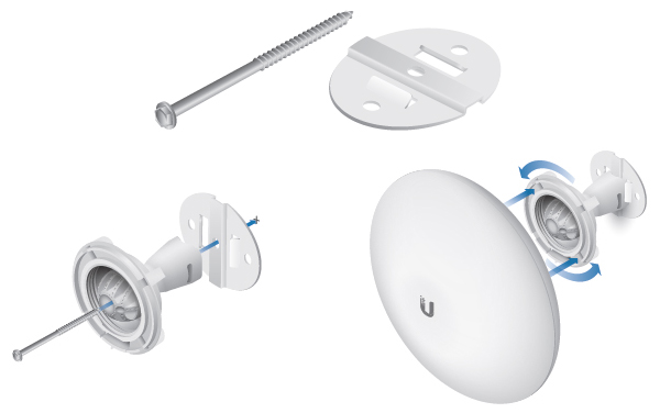
Use the optional NBE-WMK Wall Mount Kit for enhanced stability when mounting the NanoBeam on a wall.
Product Views:
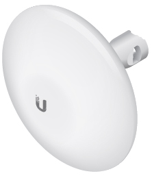
NanoBeam M2-13 (2.4 GHz, 13 dBi)
Product ID: NBE-M2-13
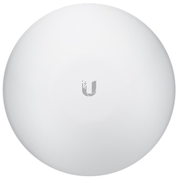
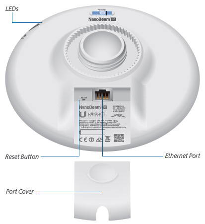
Front View
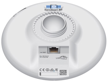
Back View
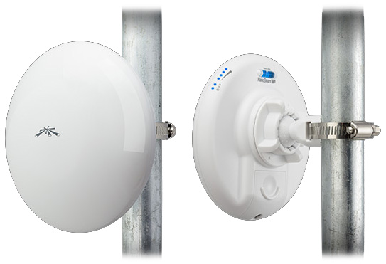
NanoBeam M5 on Port Mount

Installation Using the NanoBeamM Wall Mount Kit
Model: NBE-WMK (Sold Separately)
Specifications:
| NBE-M2-13 | |||
|---|---|---|---|
| Dimensions | 189 x 189 x 125 mm (7.44 x 7.44 x 4.92") | ||
| Weight | 0.530 kg (1.17 lb) | ||
| Power Supply | 24V, 0.5A PoE | ||
| Max. Power Consumption | 6W | ||
| Operating Frequency | 2405 - 2475 MHz | ||
| Gain | 13 dBi | ||
| Networking Interface | (1) 10/100 Ethernet Port | ||
| Processor Specs | Atheros MIPS 74Kc, 560 MHz | ||
| Memory | 64 MB DDR2, 8 MB Flash | ||
| LEDs | (1) Power, (1) LAN, (4) WLAN | ||
| Signal Strength LEDs | Software-Adjustable to Correspond to Custom RSSI Levels | ||
| Channel Sizes | 5/8/10/20/30/40 MHz | ||
| Polarization | Dual Linear | ||
| Enclosure | Outdoor UV Stabilized Plastic | ||
| Mounting | Pole-Mount (Kit Included), Wall-Mount | ||
| Wind Loading | 45.4 N @ 200 km/h (10.2 lbf @ 125 mph) | ||
| Wind Survivability | 200 km/h (125 mph) | ||
| ESD/EMP Protection | Air: ± 24 kV, Contact: ± 24 kV | ||
| Operating Temperature | -40 to 80° C (-40 to 176° F) | ||
| Operating Humidity | 5 to 95% Noncondensing | ||
| Wireless Approvals | FCC, IC, CE | ||
| RoHS Compliance | Yes | ||
| Salt Fog Test | IEC 68-2-11 (ASTM B117), Equivalent: MIL-STD-810 G Method 509.5 | ||
| Vibration Test | IEC 68-2-6 | ||
| Temperature Shock Test | IEC 68-2-14 | ||
| UV Test | IEC 68-2-5 at 40° C (104° F), Equivalent: ETS 300 019-1-4 | ||
| Wind-Driven Rain Test | ETS 300 019-1-4, Equivalent: MIL-STD-810 G Method 506.5 | ||
Operating Frequency:
| NBE-M2-13 Output Power: 28 dBm | ||||
|---|---|---|---|---|
| TX Power Specifications | RX Power Specifications | |||
| Modulation | Data Rate Avg. TX | Tolerance Modulation | Data Rate Sensitivity | Tolerance |
| 802.11g | 1 - 24 Mbps 28 dBm | ± 2 dB | 1 - 24 Mbps -94 dBm Min. | ± 2 dB |
| 36 Mbps 26 dBm | ± 2 dBQ | 36 Mbps -80 dBm | ± 2 dB | |
| 48 Mbps 25 dBm | ± 2 dB | 48 Mbps -77 dBm | ± 2 dB | |
| 54 Mbps 24 dBm | ± 2 dB | 54 Mbps -75 dBm | ± 2 dB | |
| 802.11n/airMAX | MCS0 28 dBm | ± 2 dB | MCS0 -96 dBm | ± 2 dB |
| MCS1 28 dBm | ± 2 dB | MCS1 -95 dBm | ± 2 dB | |
| MCS2 27 dBm | ± 2 dB | MCS2 -92 dBm | ± 2 dB | |
| MCS3 26 dBm | ± 2 dB | MCS3 -90 dBm | ± 2 dB | |
| MCS4 25 dBm | ± 2 dB | MCS4 -86 dBm | ± 2 dB | |
| MCS5 24 dBm | ± 2 dB | MCS5 -83 dBm | ± 2 dB | |
| MCS6 23 dBm | ± 2 dB | MCS6 -77 dBm | ± 2 dB | |
| MCS7 22 dBm | ± 2 dB | MCS7 -74 dBm | ± 2 dB | |
| MCS8 28 dBm | ± 2 dB | MCS8 -96 dBm | ± 2 dB | |
| MCS9 28 dBm | ± 2 dB | MCS9 -95 dBm | ± 2 dB | |
| MCS10 27 dBm | ± 2 dB | MCS10 -92 dBm | ± 2 dB | |
| MCS11 26 dBm | ± 2 dB | MCS11 -90 dBm | ± 2 dB | |
| MCS12 25 dBm | ± 2 dB | MCS12 -86 dBm | ± 2 dB | |
| MCS13 24 dBm | ± 2 dB | MCS13 -83 dBm | ± 2 dB | |
| MCS14 23 dBm | ± 2 dB | MCS14 -77 dBm | ± 2 dB | |
| MCS15 22 dBm | ± 2 dB | MCS15 -74 dBm | ± 2 dB | |
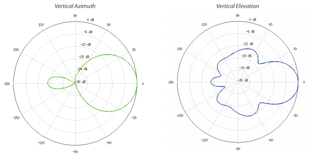
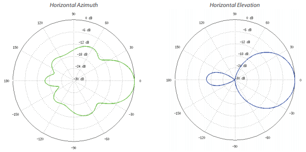
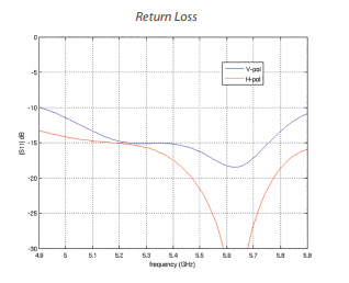
Antenna Information:
Software:
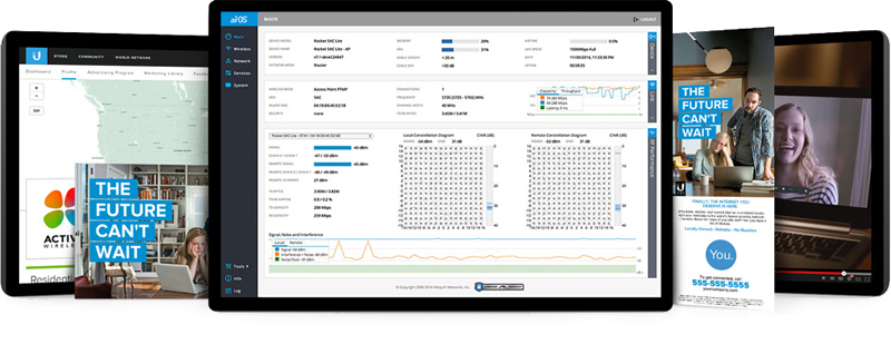

Software to Easily Manage Devices and Reach Customers
AirOS is an intuitive, versatile, highly developed Ubiquiti firmware technology that resides on Ubiquiti Station products. It is exceptionally intuitive and was designed to require no training to operate. Behind the user interface is a powerful firmware architecture which enables hi-performance outdoor multipoint networking.
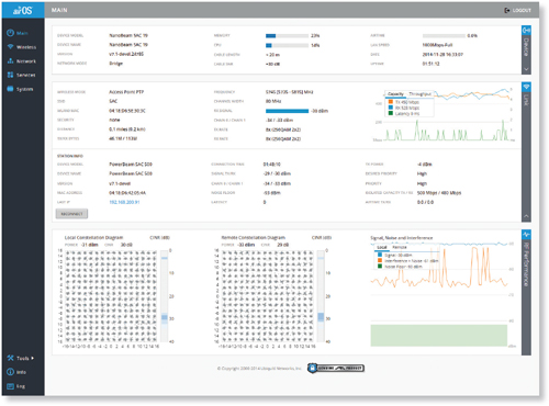 airOS Version 7
Sporting an all-new design for improved usability, airOS v7 is the revolutionary operating system for Ubiquiti airMAX ac products.
Powerful Wireless Features
- airMAX ac Protocol Support
- Long-Range Point-to-Point (PtP) Link Mode
- Selectable Channel Width
- PtP: 10/20/30/40/50/60/80 MHz
- PtMP: 10/20/30/40 MHz
- Automatic Channel Selection
- Transmit Power Control: Automatic/Manual
- Automatic Distance Selection (ACK Timing)
- Strongest WPA2 Security
Usability Enhancements
- Dynamic Configuration Changes
- Instant Input Validation
- HTML5 Technology
- Optimization for Mobile Devices
- Detailed Device Statistics
- Comprehensive Array of Diagnostic Tools, including Ethernet Cabling Test, RF Diagnostics, and airView Spectrum Analyzer
 Advanced RF Analytics
airMAX ac devices feature a multi-radio architecture to power a revolutionary RF analytics engine.
An independent processor on the PCBA powers a second, dedicated radio, which persistently analyzes the full 5 GHz spectrum and every received symbol to provide you with the most advanced RF analytics in the industry.
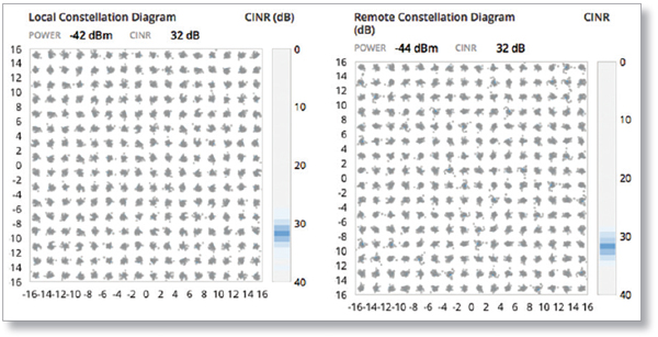
Data from the spectrum analysis and RF performance monitoring is displayed on the Main tab and airView Spectrum Analyzer of airOS V7.
Real-Time Reporting
The Main tab displays the following RF information:
- Persistent RF Error Vector Magnitude (EVM) constellation diagrams
- Carrier to Interference-plus-Noise Ratio (CINR) histograms
- Signal-to-Noise Ratio (SNR) time series plots
Persistent RF EVM Constellation Diagrams, CINR Histograms, and SNR Time Series
airMAX ac devices have an additional dedicated radio persistently analyzing the full 5 GHz spectrum and every received symbol to provide operators with the most advanced RF analytics in the industry.
Constellation Diagrams and CINR Histograms

SNR Time Series Plots
airOS Integrated Technologies
airMAX – Provides superior wireless performance, more clients per Access Point (AP), and lower latency. Unlike standard WiFi protocol, Ubiquiti's Time Division Multiple Access (TDMA) airMAX protocol allows each client to send & receive data using pre-designated time slots scheduled by an intelligent AP controller.
This "time slot" method eliminates hidden node collisions & maximizes air time efficiency. It provides many magnitudes of performance improvements in latency, throughput, & scalability.
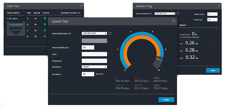
Wireless Modes
- Access Point
- Station/Client
- AP-Repeater
Wireless Network Configuration
- airMAX Mode
- airSelect Mode
- Long Range PtP Link Mode
- Mixed IEEE 802.11 Mode (A/N or B/G/N)
- WDS (Transparent Bridge Mode)
- Selectable Channel Width: 2/3/5/8/10/20/25/30/40 MHz
- Auto Channel Selection
- Channel Shifting
- Transmit Power Control: Automatic/Manual
- Automatic Distance Selection (ACK Timing)
- SSID Broadcast Disabling
- Wireless Access Control List
- Wireless Security: WEP/WPA/WPA2
- Wireless Client Isolation
- Adjustable Aggregation Frames/Bytes
- WMM
Network Configuration
- Administrator/Read-Only Access
- Location: Latitude and Longitude
- Signal LED Indication Level Management
- WEB/SSH/Telnet Access
- Block Management Access
- Dynamic DNS
- NTP Client
- Ping Watchdog
- SNMP v1 Support
- System Log: Local/Remote
- Full Statistical Performance Reporting
Network Modes
- Transparent Layer 2 Bridge
- Router
- SOHO Router
Management
- Automatic check for airOS Updates
- Configuration Test Mode
- Firmware Recovery via TFTP
- Reset to Factory Defaults
- Configuration Management: Backup/Restore
Network Configuration
- Simple/Advanced Configuration Mode
- Multiple VLANs Support
- Multiple Bridge Support
- DHCP Server/Client/Relay
- DNS Proxy
- Adjustable MTU
- PPPoE Client
- IP Aliasing: Auto/Static
- Fallback IP Support: DHCP/PPPoE
- MAC Address Cloning
- Port Forwarding (NAPT)
- Masquerading (NAT)
- Static Routing
- Multicast Routing
- Firewall: Layer 2/IPv4/IP-P2P
- Traffic Shaping: Ingress/Egress
- DMZ
- UPnP
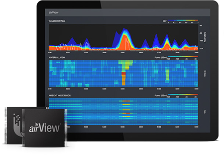

Spectrum Analyzer by Ubiquiti Networks
signatures and plan your networks to minimize noise interference. airView performs the following functions:
- Constantly monitors environmental noise
- Collects energy data points in real-time spectral views
- Helps optimize channel selection, network design, and wireless performance
airView runs in the background without disabling the wireless link, so there is no disruption to the network.
In airView, there are three spectral views, each of which represents different data.
- Waterfall Aggregate energy collected for each frequency
- Waveform Aggregate energy collected
- Ambient Noise Level Background noise energy shown as a function of frequency
Available with a firmware upgrade to airOS v7.1, airView provides powerful spectrum analyzer functionality, eliminating the need to rent or purchase additional equipment for conducting site surveys.
Waterfall Chart
This time-based graph shows the aggregate energy collected since the start of an AirView session, over time for each frequency. The power of the energy in dBm is shown across the frequency span and one row is inserted in this graph every few seconds.
It is important to note that the color of the energy designates its amplitude. The darker colors (Blues and darker shades) mean very low to low energy levels at that frequency bin, whereas increasingly brighter colors (ie: Green, Yellow, Orange, and finally Red) designate increasingly higher energy levels at the specific frequency bin.
The Waterfall View's legend (top-right corner) provides a numerical guide associating the various colors to power levels (dBm). The low end of that legend (left) is always adjusted with the calculated noise floor, and the high end (right) is set to the highest detected power level since the start of the session.

Channel Usage Chart
This graph is ideal for determining the best channel to setup a WiFi network for optimal performance. In the graph, each 2.4GHz WiFi channel is represented by a bar displaying a percentage representing the relative "crowdedness" of that specific channel.This percentage is calculated by analyzing both the popularity and the strength of RF energy in that channel since the start of a AirView session. An installer could use this view to optimize a network installation by avoiding highly used channels and setting up new AP's on channels showing the least usage.

Waveform Chart
This graph shows the aggregate energy collected since the start of an AirView Session. The power of the energy in dBm is shown across the frequency span. A Blue color will mean energy at a particular strength and frequency appears in the air with a relatively low occurence, whereas increasingly brighter colors (ie: Green, Yellow, Orange, and finally Red) designate energy appearing at a specific power/frequency with higher occurrence. The spectral view over time will essentially display the steady-state RF energy signature of a given environment. An installer could use this view to optimize a network installation by avoiding highly used channels and setting up new AP's on channels showing the least usage.

Real-time Chart
This graph displays a traditional Spectrum Analyzer in which energy (in dBm) is shown real-time as a function of frequency. There are three traces in this view: Max Hold, this trace will update and hold maximum power levels across the frequency since the start of an AirView session. Average, this trace shows the running average energy across frequency. Real-time, this trace shows the real-time energy seen by the AirView device as a function of frequency.

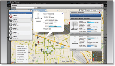

Centrally Manage 1000s of Ubiquiti Devices
AirControl is a powerful and intuitive web based server network management application which allows operators to centrally manage entire networks of Ubiqutii devices.
- Network Map - View access points and stations on a Google Road, Terrain, or Satellite Picture Map to aid in installation planning. Export to KML.
- Monitor Device Status - View status, information, and statistics of devices managed by AirControl on customizable and easy-to-read graphs.
- Mass Firmware Upgrade - Upgrade individual devices or groups of devices with synchronization for wireless association dependency.
- Web UI Access - Access the AirControl user interface through a web browser (HTTP or HTTPS); no installation is required on the client.
- Manage Groups of Devices - User-defined, dynamic, and auto device groups provide easy navigation and device management.
- Task Scheduling - Schedule tasks such as firmware update, reboot, IP range scan, device configuration backups, ping watchdog and custom commands execution.
![]()
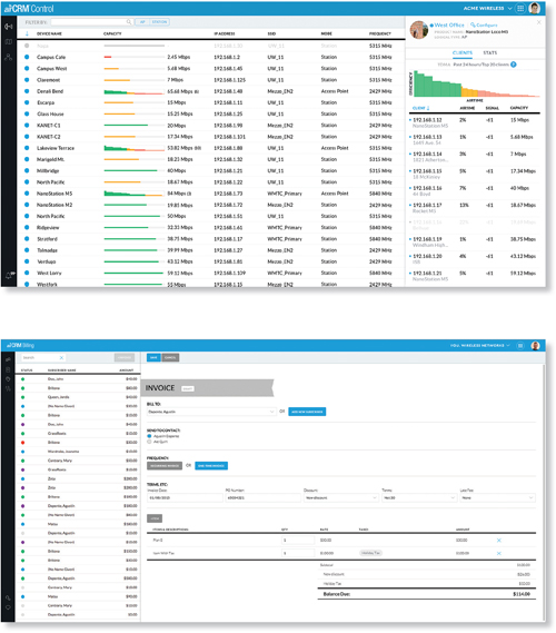
Powerfully scale your business with airCRM, a suite of WISP applications that help you manage your business. To sign up for the public beta, visit: aircrm.ubnt.com
![]()
Provision, monitor, and manage all devices from a central interface. Enjoy quicker deployments, healthier networks, and faster customer service response times.
Use airCRM Control to perform the following tasks:
- Upgrade firmware
- Manage passwords
- Monitor and analyze network traffic
- Manage devices

A streamlined billing and customer management solution delivers automated invoicing, payment reminders, and credit card processing with Authorize.Net.
Use airCRM Billing to perform the following tasks:
- Create invoices
- Manage accounts
- Enable a customer portal
- Generate detailed reports
Miscellaneous:
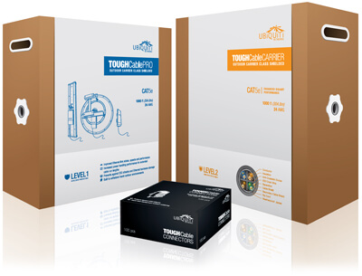

Protect your networks from the most brutal environments with Ubiquiti's industrialgrade shielded ethernet cable, TOUGHCable.
- Increase Performance - Dramatically improve your ethernet link states, speeds, and overall performance with Ubiquiti TOUGHCables.
- Extreme Weatherproof - TOUGHCables have been built to perform even in the harshest weather and environments.
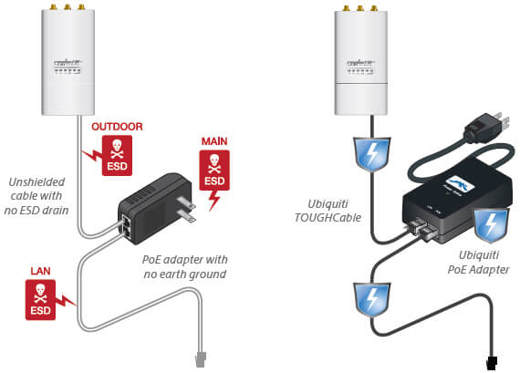
- ESD Damage Protection - Protect your networks from devastating electrostatic discharge (ESD) attacks.
- Extended Cable Support - TOUGHCables have been developed to have increased power handling performance for extended cable run lengths.
Bulletproof your networks
TOUGHCable is currently available in two versions: PRO Shielding Protection and CARRIER Shielding Protection.
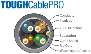
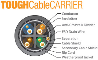
TOUGHCable PRO is a Category 5e, outdoor, carrier-class shielded cable with an integrated ESD drain wire.
TOUGHCable CARRIER is a Category 6, outdoor, carrier-class shielded cable that features an integrated ESD drain wire, anti-crosstalk divider, and secondary shielding. It is rated to provide optimal performance on Gigabit Ethernet networks.
Additional Information:
- 24 AWG copper conductor pairs
- 26 AWG integrated ESD drain wire to prevent ESD attacks and damage
- PE outdoor-rated, weatherproof jacket
- Multi-layered shielding
- Available in lengths of 1000 ft (304.8 m)
TOUGHCable Connectors
Specifically designed for use with Ubiquiti TOUGHCable, TOUGHCable Connectors protect against ESD attacks and Ethernet hardware damage, while allowing rapid field deployment without soldering. The standard TOUGHCable Connectors are available in a box of 100, while the TC-GND versions include ground wires and are available in a box of 20.
| ESD attacks are the leading cause for device failures. The diagram below illustrates the areas vulnerable to ESD attacks in a network. | By using a grounded Ubiquiti Power over Ethernet (PoE) Adapter along with Ubiquiti TOUGHCable and TOUGHCable Connectors, you can effectively protect against ESD attacks. |
 |
|

Advanced Gigabit PoE Managed Switch
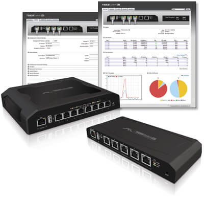
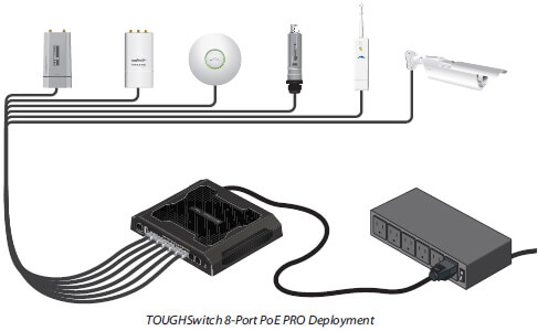
Introducing the Advanced Power over Ethernet Controllers, TOUGHSwitch™ PoE from Ubiquiti Networks. TOUGHSwitch PoE delivers reliable passive PoE and fast 10/100/1000 Mbps connectivity to attached Ubiquiti devices and other devices that support passive PoE.
To connect your PoE devices, simply enable PoE in the easy-to-use TOUGHSwitch Confi guration Interface. Each port can be individually confi gured to provide PoE, so both PoE and non-PoE devices can be connected.
Simplify Your Deployment
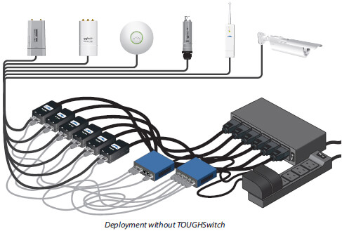
TOUGHSwitch PoE allows network architects to design cleaner, less cluttered deployments. For example, integrating one TOUGHSwitch PoE PRO can eliminate the need for the following:
- 8 PoE adapters
- 8 power cords
- 8 power outlets
- 8 Ethernet patch cables
TOUGHSwitch PoE deployments increase efficiency and greatly reduce potential failure points - resulting in faster installations and less maintenance and troubleshooting.
Documentation:
Download the Ubiquiti NanoBeam Series Datasheet (PDF).
